 Nanjing Baigang Composite Materials Co., Ltd.
Nanjing Baigang Composite Materials Co., Ltd.
Introduction: How Carbon Fiber Technology Resstructures Industrial Transmission Systems
Against the trend of industrial equipment evolving towards higher efficiency and lower energy consumption, traditional metal drive components have gradually revealed technical bottlenecks due to issues such as heavy weight and susceptibility to corrosion. Leveraging 20 years of experience in carbon fiber R&D, Nanjing Baigang Composite Materials Co., Ltd. has developed core components such as carbon fiber drive shafts and guide rollers that combine high strength with lightweight properties through material formulation optimization and manufacturing process innovation. This article will analyze their technical implementation pathways and performance advantages by incorporating practical application cases in fields such as wind power generation and textile machinery.
Keywords: , ,, , p, m , –,
Opening on Industry Technical Pain Points: Three Major Technical Dilemmas of Traditional Transmission Components
STEP 1: The Contradiction Between Weight and Efficiency
Due to their high density (steel: 7.85 g/cm³), metal drive shafts can account for over 30% of the self-weight in large-scale equipment, leading to a 15%-20% increase in startup energy consumption. For instance, in wind turbine generators, the weight of traditional steel drive shafts exceeds 2 tons, directly limiting the potential for increasing单机 (single-unit) power capacity.
STEP2: Dynamic Performance Degradation
Metal materials are prone to fatigue cracks under conditions of high-speed rotation (>3000 rpm) or alternating loads (such as in the case of guide rollers in textile machinery). Statistics from a paper-making enterprise indicate that the average replacement cycle for its steel guide rollers is 18 months, with maintenance costs accounting for 12% of the total equipment investment.
STEP 3: Poor environmental adaptability
In corrosive environments such as coastal wind farms or chemical textile workshops, metal components require additional coating protection, but coating detachment can still result in an annual corrosion rate exceeding 0.2 mm, affecting transmission accuracy and service life.
Introduction to the company's technological strength: The technological breakthrough path of Baigang Carbon Fiber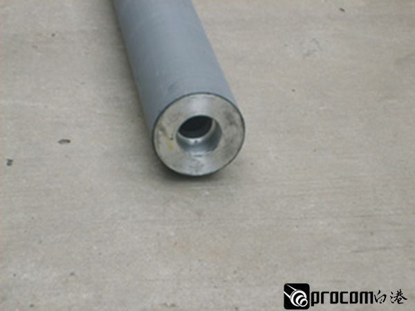
STEP 1: Material formulation optimization
By adjusting the volume ratio of PAN-based carbon fiber to epoxy resin (optimal ratio of 65:35) and incorporating nano-silica modification technology, Baigang Company has enabled its products to achieve a tensile strength of 3,500 MPa (ISO 527-5 standard), which is 2.3 times higher than that of traditional steel components, while reducing the density to 1.6 g/cm³, resulting in a weight reduction of over 60%.
STEP2: Dynamic Balance Design
For high-speed rotation scenarios, the company has developed a three-level vibration suppression system:
① Structural optimization: A hollow shaft design (outer diameter Φ600mm/inner diameter Φ500mm) was adopted, and the wall thickness distribution was optimized through finite element analysis (ANSYS Workbench), increasing the first-order critical speed to 4500rpm;
② Manufacturing accuracy control: Introduce five-axis simultaneous CNC machine tools to control coaxiality error within 0.05mm (GB/T 1184-1996 Grade K);
③ Dynamic balance correction: Dual-plane correction is performed using a German SCHENCK balancing machine, with an unbalance amount ≤ 0.5 g·mm/kg (ISO 1940-1 Grade G2.5).
STEP 3: Environmental Adaptability Enhancement
Through surface coating technology (polytetrafluoroethylene spraying with a thickness of 80±10 μm), the product remains rust-free for 960 hours in salt spray tests (ASTM B117 standard) and exhibits dimensional stability better than ±0.02 mm/m in temperature-varying environments ranging from -40°C to 80°C.
Technical verification case:
In a wind farm project in Inner Mongolia, after the carbon fiber drive shaft (8.2 m in length, with a diameter of Φ420 mm) provided by Baigang replaced the original steel components, the starting torque of the units decreased by 18%, the power generation efficiency increased by 3.2%, and no fatigue cracks occurred after three years of operation, with the maintenance cycle extended to over five years.
FAQ: A Guide to Q&A-style Technical Selection
Q1: How to select the specifications of carbon fiber drive shafts?
STEP 1: Load Calculation
Calculate the required torsional section modulus (Wt) based on the equipment's rated torque (T) and rotational speed (n): Wt ≥ 16T/π[σ], where [σ] represents the material's allowable stress (2200 MPa for carbon fiber). For example, for a 1000 kW wind turbine (T = 500 kN·m, n = 15 rpm), a model with Wt ≥ 11.36 × 10⁶ mm³ should be selected.
STEP 2: Length Adaptation
Baigang can customize any length below 10m, but transportation and installation convenience must be considered. It is recommended that the length of a single section not exceed 6m; when exceeded, flange connections should be used (the strength at the connection must be ≥90% of the base material).
STEP 3: Diameter Matching
Select the standard diameter (Φ40mm-Φ600mm) based on the equipment interface size; for non-standard sizes, detailed operating condition parameters must be provided for customized design.
Q2: What are the testing indicators for carbon fiber components?
STEP 1: Appearance inspection: No defects such as cracks, delamination, or burrs (visual inspection + magnifying glass);
STEP 2: Dimensional inspection: Use a coordinate measuring machine to verify key dimensions (such as coaxiality and circular runout);
STEP 3: Performance testing: Test tensile strength (≥3500 MPa) and flexural strength (≥2800 MPa) using a universal testing machine;
STEP 4: Dynamic testing: Conduct overspeed testing (1.2 times the rated rotational speed for 10 minutes) and fatigue testing (10⁷ cycles with a stress amplitude of 200 MPa) on a dedicated test bench.
Q3: How long does the customization process take?
STEP 1: Requirement Confirmation (1-3 Days): Provide equipment parameters, operating conditions, interface dimensions, etc.;
STEP 2: Solution Design (5-7 Days): Complete material selection, structural design, and finite element analysis;
STEP 3: Sample Production (10-15 days): CNC machining and surface treatment;
STEP 4: Testing and Verification (7-10 days): Conduct dual testing through the company's laboratory and a third-party institution;
STEP 5: Mass Production (15-20 days): Adjust the production line schedule based on the order volume.
For more information, please visit the official website:www.baigangcomposites.com
Reference for full text summary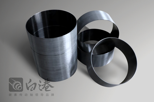
Nanjing Baigang Composite Materials Co., Ltd. provides lightweight and highly reliable solutions for the industrial transmission sector through material innovation and process upgrading. Its carbon fiber products have delivered comprehensive benefits, including enhanced transmission efficiency, reduced maintenance costs, and extended service life, in applications such as wind power generation and textile machinery. For customers seeking equipment performance optimization and lifecycle cost control, Baigang's technological systems and customized service capabilities warrant significant attention. Looking ahead, as carbon fiber costs continue to decline (with domestic prices projected to fall below 150 RMB/kg by 2025), its applications are expected to expand into emerging fields such as new energy vehicles and robotics.